Synchronous‑rectified buck converter using a coupled inductor
A DC‑to‑DC synchronous‑rectifier (SR) buck converter that uses two magnetically coupled windings on the same core to transfer energy and to generate a drive/control voltage for the synchronous (flywheeling) switch. The circuit replaces a freewheeling diode with a switch whose gate is driven via a flywheeling‑switch drive voltage control network tied to one winding’s terminal, allowing complementary switching without a complex controller. Target users are power supply designers and equipment makers integrating high‑efficiency low‑cost converters into products.
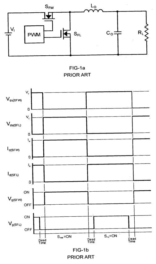
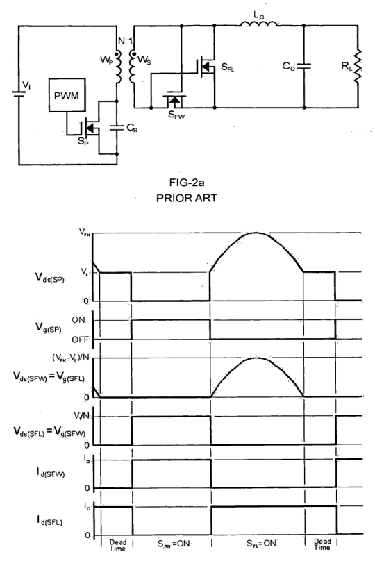
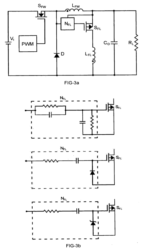
(57) What the patent covered
This write-up was generated by AI from the patent's text and may contain mistakes, so check it against the original patent before relying on it.
The main independent claim covers an SR‑buck converter with two inductor windings magnetically coupled and in the same polarity, each winding connected to opposite terminals of the smoothing capacitor; a forward switch between the input and the first winding; a flywheeling switch between the second winding and the smoothing capacitor; and a flywheeling‑switch drive voltage control network that uses the voltage at the first winding’s terminal to control the flywheeling switch so it turns on and off in the required sequence without a separate complex controller.
Distinguishing feature: Using a coupled two‑winding inductor (same polarity) with one winding providing a self‑derived control/drive voltage to operate the synchronous (flywheeling) switch, eliminating the need for a complex complementary PWM gate‑drive controller.
Novelty 3/5. Synchronous buck converters with active synchronous rectifiers were common; the new element was using a coupled inductor winding to derive the flywheeling switch drive rather than an explicit complementary gate‑drive controller, which is a refinement of SR‑buck practice.
Manufacturing
Magnetic core is wound with two insulated copper windings and potted or assembled into an inductor housing; PCB populated with MOSFETs, gate‑drive passive network, smoothing capacitor and resistive/load connections; manual or automated soldering and final electrical test.
Materials: Powdered‑iron or ferrite magnetic core with two copper windings, Copper magnet wire (enameled) for windings, MOSFETs (silicon or silicon carbide) for forward and flywheeling switches, Electrolytic or polymer smoothing capacitor.
Manufacturability 4/5. Parts are standard (wound inductor, MOSFETs, passive components); requires a winding operation for the coupled inductor and assembly of gate‑drive passive network but no specialized sensors or firmware.
Market demand
No demand check has been run for this patent. Likely search terms: synchronous buck converter coupled inductor, SR buck converter with transformer winding, coupled inductor synchronous rectifier. The links in the sidebar open these searches.
Buyers: Power supply designers and OEMs for DC‑DC modules.
Before manufacturing
No related continuation or divisional patents in force were found. Design patents, trademarks and unrelated patents may still cover the product.
Patent has lapsed; practical risks include ensuring correct magnetic coupling polarity and timing to avoid shoot‑through, meeting thermal and EMI requirements, and potential prior art or overlapping active SR topologies in the market.
This patent has reached the end of its full term and cannot be revived. This page is a research lead, not legal advice. Obtain a freedom-to-operate opinion before manufacturing.