Trolley wheel with centrifugal magnet arms that induce eddy-current braking
A trolley wheel assembly for zip-lines or coaster-type rides that uses arms with permanent magnets which swing outward under centrifugal force and move relative to adjacent non-ferrous conductive plates to generate eddy currents that oppose wheel rotation and slow the trolley. Intended users include ride operators, adventure-park owners and equipment suppliers for gravity-propelled rider conveyances.
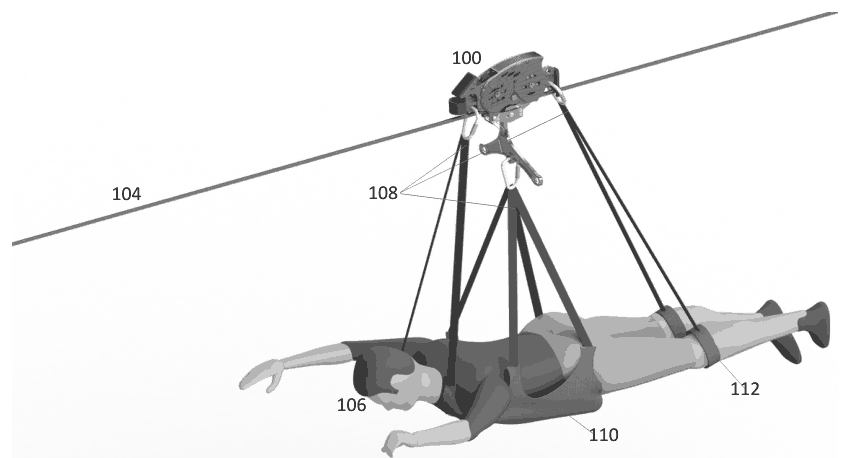
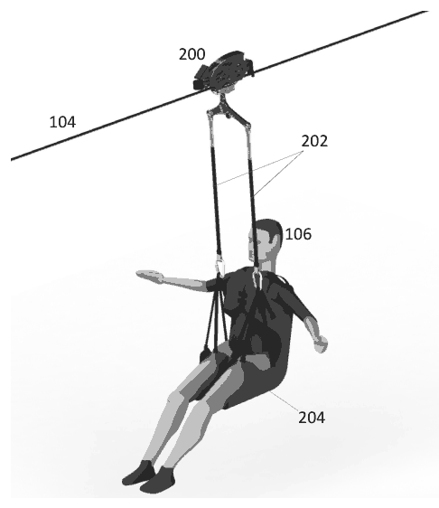
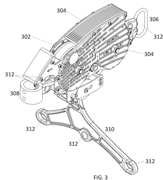
(57) What the patent covered
This write-up was generated by AI from the patent's text and may contain mistakes, so check it against the original patent before relying on it.
The main independent claim covers a rotating wheel with one or more arms that deploy from a closed to a deployed position by centrifugal force, permanent magnets mounted on those arms, and an adjacent plate of non‑ferrous conductive material positioned so that relative movement between each magnet and the plate generates eddy currents that oppose wheel rotation; the plate has at least two sections at different distances from the magnet surfaces so braking changes as arms move.
Distinguishing feature: Magnets are mounted on centrifugal arms that change proximity to a multi‑section non‑ferrous conductive plate as the arms deploy, varying eddy‑current braking with wheel speed.
Novelty 4/5. Eddy‑current braking and magnet‑to‑conductive plate brakes were known; the novelty was applying centrifugal deployable magnet arms and multi‑section plate geometry to vary braking with rotation speed.
Manufacturing
Stamped or laser‑cut conductive plate, injection‑molded or stamped arms, bonded/fastened magnets to arms, wheel assembly with standard bearings; assembled with mechanical fastening and press‑fit or bolted hubs.
Materials: Aluminum or copper non‑ferrous conductive plate, Permanent magnets (rare‑earth or ferrite), Stamped steel or molded polymer arms, Steel or aluminum wheel hub.
Manufacturability 4/5. Several simple parts (plate, arms, magnets, wheel) requiring stamping/molding, magnet bonding and standard wheel/bearing assembly; moderate hand or machine assembly.
Market demand
Comparable products are on sale; this exact design was not found. Multiple vendors advertise non-contact eddy-current braking trolleys for zip lines, including both integrated systems and modular braking components; at least one US-based vendor lists a fixed price for a braking trolley kit.
- Head Rush zipSTOP IR Braking System · Head Rush Technologies$6,468.00
- HS Magnetic zipline trolley · Zip-Rush
- ZIPLINE MAGNETIC TROLLEYS · Neodymius
Demand check by web search, week of Oct 12, 2026. Listings change frequently.
Buyers: Zip‑line and adventure park operators; ride equipment suppliers.
Sourcing
Factories list related products that could be adapted. These Made-in-China listings show magnetic braking devices integrated with hoist/trolley hardware (not a dedicated zipline eddy-current trolley). They illustrate related concepts (magnetic braking, trolley integration, OEM/PRIVATE LABEL potential) but do not show a cataloged zipline eddy-current trolley as described. Availability, exact product fit, and customization would require direct supplier confirmation.
- Giant Lift Co., Ltd. (Made-in-China listing for Motor Trolley Type... · https://www.made-in-china.com/product/rZhaGDwOffVv/China-Motor-Trolley-Type-5-Ton-Electric-Chain-Hoist-with-Trolley-Giant-Lift-Chain-Block-HHBD-I-5T-.html · MOQ contact for pricenot listed
- Vanbon (Made-in-China listing for 5 Ton Electric Chain Hoist with Trolley) · https://www.made-in-china.com/product/lXUmsDtGvLhp/China-5ton-Electric-Chain-Hoist-Single-Speed-WBH-05002SE-.html · MOQ contact for pricenot listed
- Seagull (Made-in-China listing for Electric Chain Hoist with Trolley) · https://www.made-in-china.com/product/UYzpSOlrbAhF/China-Seagull-0-5-10-Ton-200-600V-380V-Electric-Chain-Hoist-with-Trolley.html · MOQ contact for pricenot listed
Supplier prices are from public listings found by web search, quoted before customization, shipping and duties. Use them to decide whether to request a quotation.
Before manufacturing
No related continuation or divisional patents in force were found. Design patents, trademarks and unrelated patents may still cover the product.
Patent lapsed; practical issues include heat dissipation in conductive plate, wear of moving arm pivots, magnetic material sourcing, and verification that system meets local ride safety standards and certifications.
About 1.5% of lapsed patents are later revived by their owners. This page is a research lead, not legal advice. Obtain a freedom-to-operate opinion before manufacturing.